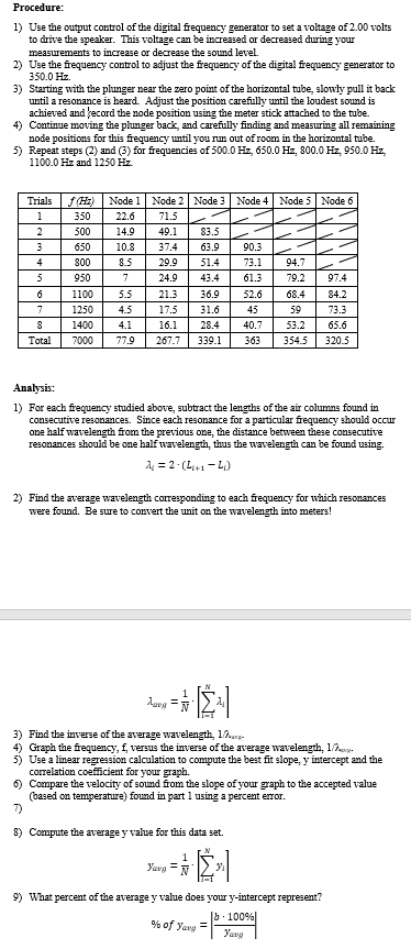
channel Digital Signal Generator DDS Function Generator Frequency Circuit Diagram Learn how to make a square wave signal generator. With step by step instructions on how to calculate and change the frequency of the square wave. Signal generator with ESP32. A signal generator is a fundamental instrument in electronics, used to produce waveforms of various frequencies and amplitudes. DIY Function/Waveform Generator: In this project we will have a short look at commercial function/waveform generators in order to determine what features are important for a DIY version. Afterwards I will then show you how to create a simple function generator, the analog and digit…

The RF signal generator is a must to have tool when playing with radio receivers. It is used to tune a resonant circuits and adjust the gain of different RF stages. Very useful feature of the RF Signal generator is its modulation capability. If it can modulate the frequency amplitude or frequency makes it non replaceable tool for RF design works. Some time ago I have designed an AM modulator WHAT IS THISLearn how to make a DIY frequency generator circuit using only a couple of components. RESOURCES Frequency Generator Schematic - https://drive
DIY Function/Waveform Generator : 6 Steps (with Pictures ... Circuit Diagram
This is a simple function generator that works in the audio frequency range. It can be useful for amplifier testing, experimentation in digital signal processing (DSP) and electronics labs. The author's prototype is shown in Fig. 1. Fig. 1: Author's prototype for Arduino based frequency generator Circuit diagram of the sine, square and ramp Arduino-based frequency generator is shown in Fig The signal generator design should include the capability to adjust signal frequency and amplitude. Moreover, devise and develop a frequency counter capable of displaying frequency of the signal being
A DDS function generator is a digital arbitrary waveform generator, meaning it uses a digital-to-analog converter (DAC) to build a signal. It also has read only memory (ROM) where it stores amplitude values for specific waveforms at various time intervals based on a sampling frequency (Fs).