101 Electrical Engineering Interview Topics Circuit Diagram The output of this inverter is used to control the desired motor, whose speed need to be controlled as per the VFD rules. In order to convert this square wave inverter into a sine wave VFD circuit, I have configured an adjustable SPWM generator stage using the IC 555 astable and an op-amp comparator.

Variable Frequency Drive (VFD) - Circuit Diagram, Working, Types, Advantage, Disadvantages, and Applications. Types of VSI, CFI and PWM VFDs. Breaking News. 50% OFF on Pre-Launching Designs - Ending Soon ; Special Motor Design: The PWM-based AC output of VFD is not pure sinusoid. It can create stress in the windings of a normal AC motor
Inside Variable Frequency Drive (VFD) Panel: Configuration ... Circuit Diagram
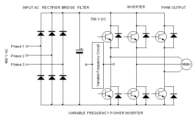
This paper describes the design processes for a 3-Phase Variable Frequency Drive (VFD) as broken up into two stages: The AC-DC converter and the DC-AC converter. It acknowledges three (3) design Figure 2.1 Rectifier circuit (discreet component design) For simplicity, I have opted to use a pre-packaged 3-phase rectifier from Vishay
Step 3: Design the Power Circuit. Design the power circuit of the VFD schematic, which includes the rectifier, DC bus, and inverter sections. Determine the appropriate component values, such as capacitor size and inductor ratings, based on the system's power requirements and desired performance. Step 4: Develop the Control Circuit
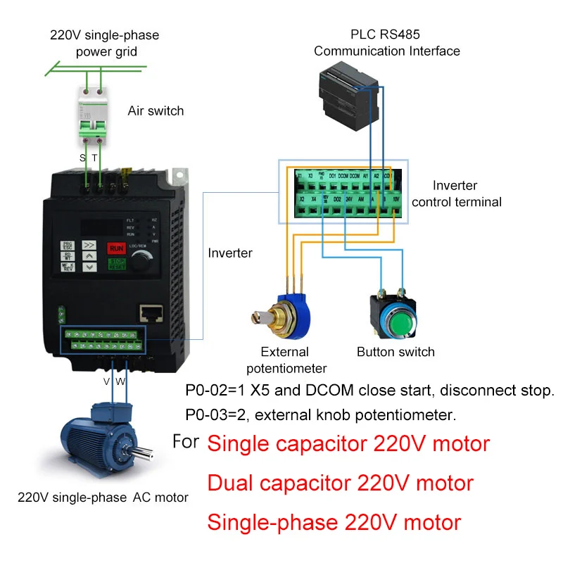
VFD (Variable Frequency Drive) Circuit Diagram
Design the control circuit: Select a microcontroller or control IC that can generate the necessary PWM signals for the inverter. Design the gate driver circuits to interface the control signals with the inverter switches. Implement any necessary feedback and control algorithms (e.g., V/Hz control, sensorless vector control). Assemble the VFD: The VFD circuit diagram may also include additional components, such as capacitors, resistors, diodes, and filters, depending on the specific design and requirements of the system. These components are used to ensure proper power conditioning and to protect the VFD system from voltage spikes and other electrical disturbances.
